
Intro to Macro Programming
Macro Intro
Macro programming is another tool in the machinist’s toolbox. This tool resides in the CNC control, and its purpose is to write code in an automated way. Macro programming allows the use of parameters or variables in the code which can be filled with user-entered values that can change with a simple macro program call. For example, if you have a family of parts that are similar in shape but differ in size, the program can be written with the addition of macros and had the ability to update with just a few changes of values in the code.
Macro programming is considered parametric programming, because you pass it parameters which the programmer can use to calculate the tooling positions. It’s the closest thing CNC programmers have to higher level languages such as C++ and Python, for instance. It differs from regular G code programs by the use of variables, arithmetic, loops, branching, and data storage, to name a few.
Macro is typically an often installed option but it not always used. How do you know if you have it? Write the following program in MDI mode and hit cycle start:
#1=0
No alarm? The macro option is installed in your control.
Macro is typically an option that resides in the CNC control for brands like HAAS and Fanuc, which this article focuses on. Other machine tool controls have similar functionality, but are beyond the scope of this article.
Instead of defining a long list of necessary functions and abilities of Macro programming first, let’s jump right into an example to see what the code looks like, and some of things you can do.
Let’s say we want to side mill a block with multiple passes along the X axis with a ½” end mill:

Figure 1: The macro toolpath pattern of milling a block.
Here’s the code:
#2=0.2
G0 Y#2 X-0.5
Z0.5 (Point 1 before the loop)
WHILE[#2 GE -0.25] DO2
G0 Y#2 X-0.5 (Point 1 subsequent loops)
Z-0.75 F50. (POINT 2)
G01 X5. (Point 3)
G0 Z.5 (Point 4)
#2=#2-.05
END2
In this code the first thing that sticks out to newcomers is the use of a variable with #2 in the first line. In the macro language, all variables are designated with a # and number (more on variables later). In the first line, variable #2 has been set equal to 0.2. The other oddity in the code that jumps out to G code users is the WHILE[..] DO2 line with the END2 at the finish. These two lines are connected. The WHILE statement is a loop which repeats while a condition is met. Once the condition fails, the program jumps to END2 and ends the loop. In this example, the condition is #2 GE -0.25 which reads as follows: while #2 is greater than or equal to -0.25, repeat the code between the WHILE statement and END2. With every turn of the loop, -0.05 is subtracted from #2 with the line #2=#2-.05. This subtraction causes a 0.05 stepover in Y with every iteration of the loop.
Let’s further walk thru the entire loop, starting from the beginning. After #2 is defined as 0.2, the WHILE statement asks itself, is 0.2 greater than -0.25? Yes it is, so DO2. The tool moves to Y0.2 X-0.5, then Z0.1 and so on all the way thru to G0 Z0.5. Notice the value of #2 changes by -0.05 right before the end of the loop with the code #2=#2-.05. In the second iteration of the loop, the WHILE statement is again satisfied with #2=0.15, and the tool repeats the pattern again. This repeats until the 10th loop when #2=-0.25, the WHILE condition is again satisfied and #2 is reduced to -0.3. Now, with #2=-0.3, the WHILE condition is not true because #2 is less than -0.25, and the loop jumps to END2.
This is some really basic macro code which is useful in small everyday situations. It makes a simple, repeated process easy to program by hand at the control. Let’s try a loop within a loop next, but first it’s probably best to define some loops and logical operators available in the macro language.
IF Statement and WHILE Loops
There are two conditional phrases that work in macro. IF and WHILE. The following are examples of each.
Example 1: IF statement
IF [1GT2] #1=10
The IF statement reads as follows: IF 1 is greater than 2 then set variable #1 to a value of 10. Of course, one is not greater than 2, so the #1=10 part never happens in this case and the program would move on to the next line.
Example 2: WHILE statement
WHILE [#10GT2] DO2
…
END2
The WHILE statement is shown in the example above. To summarize, the code between D02 and END2 repeats until the statement in the brackets is no longer true. The DO2 and END2 statements are matched and will only work together. Within the loop there is often a change made to the variable in the WHILE statement, otherwise the loop would go on indefinitely. For example, the change to variable #10 with the line #10=#10+1. Keep in mind that the loop can be infinite and never stop if the condition is never broken with a variable value change. For example:
#1=10
WHILE[#1LT20] DO1
G0 X0 Y0
Z0.1
G01 Z-0.5 F10.
G0 Z1.
END1
In this section of code, the loop would go on indefinitely because there is no change to the value of #1 and it will always have the value less than 20.
Square Brackets
Square brackets work in pairs and take priority over operations outside of the brackets. Brackets can also be nested within another pair of brackets and the innermost ones should be calculated first. For example, the result of the following code is changed because of the brackets involved:
without brackets 7+2*4 = 56
With brackets [7+2]*4 =36
Operators
There are six available logical operators used in macro:
| Math Character | Definition | Macro Code |
|---|---|---|
| = | Equal to | EQ |
| ≠ | Not equal to | NE |
| < | Less than | LT |
| > | Greater than | GT |
| ≤ | Less than or equal to | LE |
| ≥ | Greater than or equal to | GE |
| Definition | Macro Code | Example | Result |
|---|---|---|---|
| Addition | + | [5+2] | 7 |
| Subraction | - | [5-2] | 3 |
| Multiplication | * | [5*2] | 10 |
| Division | / | [5/2] | 2.5 |
| Square Root | SQRT[] | SQRT[16] | 4 |
| Absolute Value | ABS[] | ABS[-5] | 5 |
| Sine | SIN[] | SIN[45] | 0.707 |
| Cosine | COS[] | COS[10] | 0.984 |
| Tangent | TAN[] | TAN[45] | 1 |
| Inverse Sine | ASIN[] | ASIN[0.707] | 45 |
| Inverse Cosine | ACOS[] | ACOS[0.984] | 10 |
| Inverse Tangent | ATAN[] | ATAN[1] | 45 | Rounding | ROUND[] | ROUND[0.5] | 1 | Round Up | FUP[] | FUP[1.2] | 2 | Round Down | FIX[] | FIX[1.99] | 1 |
Variables
Variables in the control act as place holders to store data. Once the variable data is entered, it can later be called on. There are several categories of variables and they vary between models and brands of controls. It’s important to determine the variable definitions for your specific machine to know which of the following categories they apply to. Please consult your machine manual for further clarification.
Local variables, These are temporary, and have their values deleted when the control RESET is pressed, during a power off, when M99 or M30 is run. They are also used as macro call arguments which is beyond the scope of this article. #1-#33 for both HAAS and FANUC.
Global variables. These variables continue to store data even when the control is powered down, RESET is pressed, M30 is run, or M99 is run. They’re designed to be used by more than one macro program. For Fanuc, #100-#149 and #500-#531. For HAAS, #100-#199, #500-#699 and #800-#999. Note: Some machine accessories use some of the global variables which you won’t want to use as common practice. One such accessory is a touch probe or tool setting probe. For HAAS, #156-#199 and #556-#599 are used by Renishaw’s probe(s).
System variables. These variables store machine data that you typically don’t want to change, but may want to read. Be extremely careful with making changes here. The list of system variables is quite long and varies by machine manufacturer. You’ll definitely want to consult your machine manual. #1000 and up for Fanuc and HAAS.
Loop Within A Loop
A loop can be used within a loop to increase functionality in a program. For example, say we take our side milling program and use it at multiple Z levels after the Y axis stepover is complete:
#1=-0.75
WHILE[#1 GE -1.5] DO1
#2=0.2
G0 Y#2 X-0.5
Z0.5
WHILE[#2 GE -0.25] DO2
G0 Y#2 X-0.5
Z#1
G1 X5.
G0 Z.5
#2=#2-.05
END2
#1=#1-0.75
END1
This short program takes 10 passes (just like example 1) at the Z-0.75 level and then another 10 passes at the Z-1.5 level. The program starts by defining another variable, #1 equal to -0.75 and starts the first WHILE loop, DO1. Then it defines the variable #2 as 0.2 and starts a second WHILE loop (exactly like example 1). Once all the passes are finished in the DO2 loop, the DO2 loop ends and the first loop takes over with the #1=#1-0.75 line. The DO1 loop then starts over with #1 now equal to -1.5. The WHILE[#1 GE -1.5] DO1 condition is satisfied and #2 is reset back to 0.2 with the #2=0.2 line. Then, the DO2 loop runs 10x once again and kicks back out to the #1=#1-0.75 line. The DO1 loop starts again. Now, the DO1 loop then tests the condition with #1 equal to -2.25 which is less than -1.5, so it kicks to the END1 line where the loop ends. It’s important to note that the variables and loop numbers I chose are a little bit random and they do not need to match. For example, the #5 variable could be used instead of #1 and the #7 variable could be used instead of #2. The only match up needed is DO1 with END1 and DO2 with END2. It’s possible to use loops up to 3 levels deep, i.e., a loop within a loop, within a loop.
You may have guessed already, but the nested loops need to increase. In other words, DO1 must be first, then DO2 and DO3. DO1 cannot be nested inside DO2.
Macros with Calculations
So far we’ve only used macro code to run loops with predefined start and end points, but we can also calculate positions based on certain options we decide we want to keep flexible. For this example, with use light stepovers to open a slot, sometimes known as trochoidal milling or peel milling. It follows a toolpath as shown in Figure 2.
We’ll write a simple loop to execute the program in the first iteration and then add in some options (size of tool, radius, and width of slot) later. We’re going to use a ½” end mill, with a 0.05” stepover, the slot is 1.5” wide and 3.00” long. The center of the slots is a Y0, and we’re going to use a climbing path to mill the slot from bottom to top (from the Y- to the Y+ direction).
The tool path is going to enter at the bottom (Y-) of the slot. Note that we use 0.1” of distance between positions 1 and 2 which you’ll see in the Position 1 calculation.

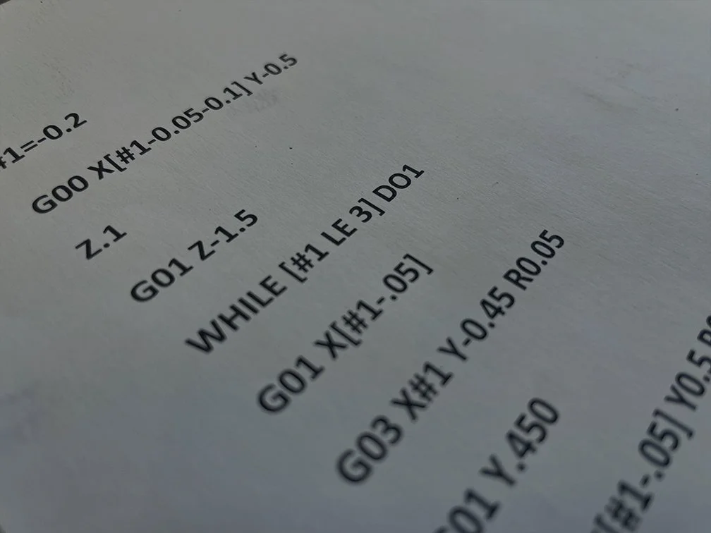
Figure 2: Peel milling toolpath. +Z direction is out of the page
#1=-0.2
G00 X[#1-0.05-0.1] Y-0.5
Z.1
G01 Z-1.5 (Position 1 before the loop)
WHILE [#1 LE 3] DO1
G01 X[#1-.05] (Position 2)
G03 X#1 Y-0.45 R0.05 (Position 3)
G01 Y.450 (Position 4)
G03 X[#1-.05] Y0.5 R0.05 (Position 5)
G00 Y-0.5 (Back to Position 2)
#1=#1+0.05 (Stepover)
END1
Now the above can be done other ways. For instance, repeating a subprogram using M98 and using G91 instead of the typical G90. Both methods could allow a change of stepover with repeats. However, where macro shines is in the ability to add calculations and use variables to easily make changes. Let’s expand on this example by adding the end mill diameter and the stepover as variables. We need to change the program a bit since we need to define and store some variables first:
#100=0.5 (End mill size variable)
#110=0.05 (Stepover)
#101= [1.5/2]-[#100/2] (No 5 Y position calculation)
#102=[-[#100/2]+#110] (No 3 X position calculation)
G00 X[#102-0.05-0.1] Y-#101 (Position 1)
Z.1
G01 Z-1.5
WHILE [[#102-.05] LE 3] DO1
G01 X[#102-.05] (Position 2)
G03 X#102 Y[-#101+.05] R.05 (Position 3)
G01 Y[#101-.05] (Position 4)
G03 X[#102-.05] Y#101 R.05 (Position 5)
G00 Y-#101 (Back to Position 2)
#102=#102+#110 (Stepover)
END1
First, we define the end mill size in the #100 variable and the stepover in variable #110. Next, we calculate the Y value at the No 5 position and store in the #101 variable. Then we calculate the No 3 X position and store in the #102 variable. These reference positions are a bit random. I chose the No 5 Y position because it was the position at the full slot width and the #102 X position as the first step over in cut. The rest of the program is written in reference to these positions so that the toolpath is calculated with every loop. Right before END1, the No 3 X position is changed with a 0.05 stepover. Note that the value of 0.1 in the Position 1 line calculation is a clearance of 0.1 away from position 2, which was chosen at random.
With the toolpath written this way, all the user has to do is change the end mill size in variable #100, or the stepover in variable #110 and the program will update automatically.
Now, let’s add another option: the enter and exit radius. It’s currently R.05 or 10% of the end mill diameter. We’re going to define variable #103 and use it in the position calculations where needed:
#100=0.5 (End mill size variable)
#110=0.05 (Stepover)
#103=0.1*#100 (Enter and Exit radius)
#101= [1.5/2]-[#100/2] (No 5 Y position calculation)
#102=[-[#100/2]+#110] (No 3 X position calculation)
G00 X[#102-#103-0.1] Y-#101 (Position 1)
Z.1
G01 Z-1.5
WHILE [[#102-#103] LE 3] DO1
G01 X[#102-#103] (Position 2)
G03 X#102 Y[-#101+#103] R#103 (Position 3)
G01 Y[#101-#103] (Position 4)
G03 X[#102-#103] Y#101 R#103 (Position 5)
G00 Y-#101 (Back to Position 2)
#102=#102+#110 (Stepover)
END1
Once again, we’ve automated another option in the program, so if the user would like to use a larger or smaller radius size, they can easily change variable #103 and the program will automatically update.
Let’s add one more variable, the slot width:
#100=0.5 (End mill size variable)
#110=0.05 (Stepover)
#111=1.5 (Slot width)
#101= [#111/2]-[#100/2] (No 5 Y position calculation)
#102=[-[#100/2]+#110] (No 3 X position calculation)
#103=0.1*#100 (Enter and Exit radius)
G00 X[#102-#103-0.1] Y-#101 (Position 1)
Z.1
G01 Z-1.5
WHILE [[#102-#103] LE 3] DO1
G01 X[#102-#103] (Position 2)
G03 X#102 Y[-#101+#103] R#103 (Position 3)
G01 Y[#101-#103] (Position 4)
G03 X[#102-#103] Y#101 R#103 (Position 5)
G00 Y-#101 (Back to Position 2)
#102=#102+#110 (Stepover)
END1
Now we have automated the stepover, end mill size, slot size and entry/exit radius all which can quickly and easily be changed by an operator at the machine.
Alarms and the GOTO statement
Another macro function which is quite useful is the ability to add alarms if the operator enters variables that are outside the range that the programmer intended. For example, in our trochoidal milling program above, if an end mill size was entered larger than the slot width and entry/exit radius would allow, it could cause the toolpath to misbehave.
The format for alarms is as follows:
#3000=1 (Tool too large)
Think of #3000 as the alarm variable which is always necessary as is the number (in this example it’s 1 but could be any number up to 200). The message (Tool to large) is optional, but as you can see it’s quite useful.
Typically, the way an alarm is called is with a GOTO statement, which allows the control to skip to different numbered lines in the code. For example: GOTO200 would search for the line N200 and continue from there.
With these two function in mind, let’s add an alarm to our previous code:
#100=0.5 (End mill size variable)
#110=0.05 (Stepover)
#111=1.5 (Slot width)
#101= [#111/2]-[#100/2] (No 5 Y position calculation)
#102=[-[#100/2]+#110] (No 3 X position calculation)
#103=0.1*#100 (Enter and Exit radius)
IF[#111 LE [#100+[2*#103]]] GOTO100 (Tool size check)
G00 X[#102-#103-0.1] Y-#101 (Position 1)
Z.1
G01 Z-1.5
WHILE [[#102-#103] LE 3] DO1
G01 X[#102-#103] (Position 2)
G03 X#102 Y[-#101+#103] R#103 (Position 3)
G01 Y[#101-#103] (Position 4)
G03 X[#102-#103] Y#101 R#103 (Position 5)
G00 Y-#101 (Back to Position 2)
#102=#102+#110 (Stepover)
END1
GOTO101
N100 #3000=123 (Tool is too large for slot and entry/exit rads)
N101
Here we’ve added a line to check if the slot width is less than or equal to (LE) the tool diameter plus twice the entry rads. If yes, the program will skip to line 100 and the alarm is generated. If not, the program will continue as usual but notice there is also a GOTO101 line right before the N100 line. This GOTO101 will skip over the alarm line. If GOTO101 was not there, the alarm would generate by default.
If you enjoyed this article and would like to learn more check out more information with our Advanced Macro Programming article which deals with the G65 call creating stand alone macro programs, creating custom G codes, and advanced probing.
Amco uses Macro language on a daily basis to automate our programming process. Contact us today to learn more about our machine shop and how we can help you with your machined parts.