
Introduction to Milling
This article continues from our Introduction to Turning article and follows a very similar structure.
Milling is a process where the part being machined remains stationary and a rotating cutting tool moves along the part to create its net shape. The machine used for this process is called a milling machine. Milling is the world’s most common machining process because there is a near infinite amount of shapes its able to produce. In fact, a part that is turned on a lathe can often be machined on a milling machine, just not as efficiently. Examples of milled parts include engine blocks, aero structures and artificial hip joints.
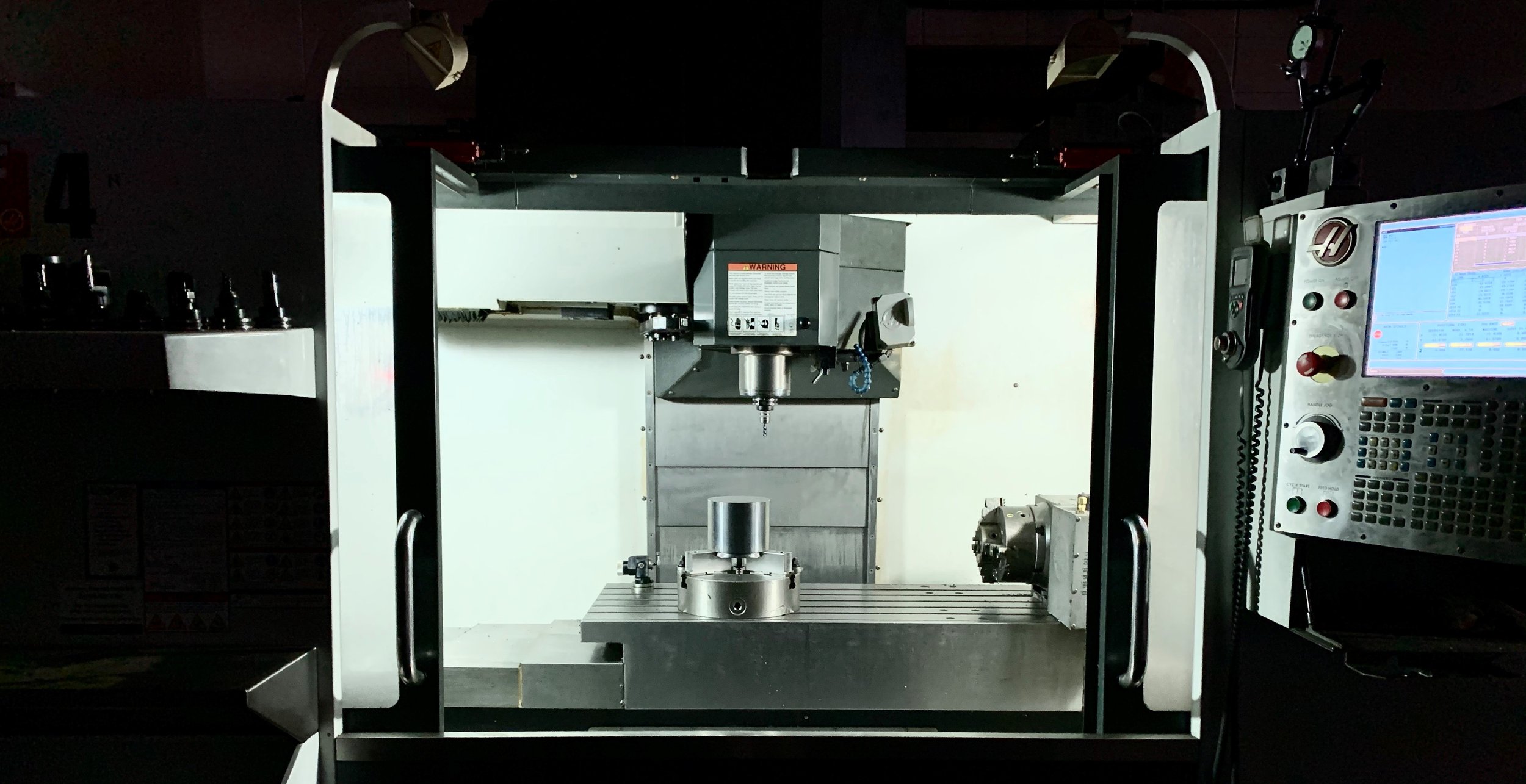
Modern milling machines are often separated into two categories: horizontal and vertical. Horizontal machines have the tool positioned horizontal (parallel) to the floor and a vertical machine’s tool is vertical (perpendicular) to the floor. An example of a vertical, double column milling machine with its sheet metal and control panel removed is shown in Figure 1 below. The machine has 3 axes: X, Y and Z


Figure 1: A vertical, double column, cnc milling machine
The following references Figure 1 above.
A milling machines foundation is called it’s bed or casting
A spindle motor in the Z axis housing drives the cutting tool
The part being machined (yellow in color) is clamped is held in a vice (blue and grey), which is clamped to the table
Controlling movement
The milling machine depicted in Figure 1 is computer numerically controlled (CNC) which means a computer signals electric motors to rotate, which in turn cause movement thru the use of ball screws. A ball screw causes movement by rotating a threaded rod inside a nut. As the rod rotates, the nut (attached to each axis) moves along the rod. The machinist would direct the movement thru use of code which he or she enters and is specific to each part.
Current CNC machines are very precise and accurate. They are able to repeatedly move and return to a location window as small as 0.0002”. Compare that to a human hair which measures about ten times larger (0.002”).
CNC Code
Typical milling machine code uses a 3 dimensional X, Y and Z grid to position the cutting tool anywhere in the machine envelope and move at specified feed rates. The code can also turn on the spindle, turn on the coolant and interface with auxiliary devices. A coding language named G code is widely used in the industry. It gets its name from the frequent use of the letter G.
In the following example, let’s examine the code used to cut a 0.25 deep slot across the middle of a block of material. We’ll select the tool we need, turn on the spindle and coolant, quickly move the tool close to the workpiece, feed the tool at our select parameters and rapid the tool back to its home position. The material being cut is 5.0” in the X axis direction, 4.0” in the Y axis direction and 1.0” thick in the Z axis direction. The origin of these axes is the top left of the block
T1 H1 G43 M06 Choose tool 1, it’s geometry (H1 and G43) and make a tool change (M06)
S3000 M03 spin the tool clockwise at 3000 RPM
M08 coolant on
G00 X-0.5 Y-2.0 move the tool to X-0.5 and Y-2.0. The X position provides clearance
Z1. bring the tool down, 1.0” away from the part in the Z direction
G01 Z-0.25 F10. feed the tool to Z-0.25” at 10 inches per minute (ipm)
G01 X5.5 F20. feed the tool all the way across the part in the X axis direction at 20ipm
G00Z0.1 move the tool up and away from the part
G00 G28 rapid all axes to the home position
M05 stop the spindle
M09 turn off the coolant
M30 end the program
Although on a milling machine a lot of code is entered point by point as in the example above, canned cycles, which are programming shortcuts built into the control, are often used to ease programming. Canned cycle examples include, drilling, tapping and boring. There are also handy functions which allow the rotation and mirroring of geometry.

Figure 2: CAD/CAM programming screen shot.
CAD/CAM programming
A CNC machine can either be programmed using the control panel or using a PC and computer aided drafting/computer aided manufacturing (CAD/CAM) software. The resulting code from the CAD/CAM software is then downloaded into the control. CAD/CAM advantages include more programming options, file organization and automation of the CNC code. In the software, the component is drafted or imported and then tool and tool paths are chosen with the software generating the code. A screen shot of milling machine toolpaths being applied to a lego shape are shown in figure 2.
Setup
Setting up the machine tool (setup) is the first phase of machining followed by the part run. Depending on the part, there may be mulitple or only one run and setup phase. During the setup phase, the machinist chooses and loads tools into the mill and secures the material using work holding (see more about work holding below) such as a vise onto a table. The part’s origin is set and the tool geometry is entered into the control. If the program is new, a cautious execution of the new program, known as a proving out the program, takes place. During the prove out, the machinist ensures that the tools cuts as expected and movements are correct. After the program is completed, the first part is measured to ensure compliance to the drawing. If any problems are detected such as part movement, programming errors or tool chatter, the issue is dealt with during this stage to setup a smooth run phase.
Run
After the setup phase the run phase of production follows. During the run phase, the program is executed on each part. The machinist is responsible for measuring part features, replacing cutting tools when necessary, and keeping the work envelope free of chips.
Tooling
A machinist’s job is to use his or her knowledge of tools to machine parts. These tools all have different functions: work holding, cutting tools, measuring tools and the machine tool. The larger the knowledge base of the tools available to a machinist, the more efficiently the part can be produced.
Tool Materials
In the milling process, the cutting tool is harder than the material it is cutting. Typically, modern cutting tools are made of tungsten carbide or WC, which is a mixture of WC and cobalt that is then heated, pressed and ground into shape. The cutting tool is often coated using physical vapor deposition (PVD) and chemical vapor deposition (CVD) depending on the application. Other tool materials such as high speed steel, cobalt, ceramic and diamond are also available. Most milling cutting tools are cylindrical in nature with one or more cutting teeth. These tools may be either indexable or solid. A solid tool has its teeth ground from a solid round bar and often kept under Ø1.00”. Indexable tools are used for larger sizes, Ø1.00+, where using a solid carbide tool would be too costly. In an indexable tool the body is steel and only the comers of the teeth are tungsten carbide. The teeth of an indexable tool can be replaced once worn and a solid tool can either be reground or tossed depending on the cost.

Figure 3: A 3 flute, solid end mill
Toolpaths
A toolpath is a pattern which the tool follows to remove material a certain way. There are several toolpaths common to milling,
slotting – using the full diameter of an end mill to cut a slot. For example, a Ø1/2” diameter end mill cutting a 0.25” depth.
shouldering – using an end mill to overlap the material, but not the full diameter as in slotting. For example, using a Ø1/2” diameter end mill to cut a 0.25”wide and 0.5” deep shoulder.
plunging – using an end mill to cut while moving in the negative Z axis. Causes the forces to push into the spindle resulting in more productivity
high speed machining – a specific type of shouldering where the amount of end mill and material overlap is small, usually 5-10% of end mill diameter with increased feeds and speeds. The length of the tool used in the cut is long, 2-3x diameter. For example, using a Ø1/2 end mill, with a 0.05” step over (10%) and 1.5” deep.
facing – using a large diameter cutter to cut a small amount of material in the Z axis direction. An example of facing would be using a Ø4.00” diameter cutter to remove 0.125” off the side of a block.
surfacing – using an end mill with a rounded end to remove small amounts of material along an organic shaped surface. Uses a lot of and code calculated using CAD/CAM.
thread milling – using a end mill with ground teeth corresponding to the pitch of the thread. The toolpath cuts a thread moving around a boss or a hole.
tapping – uses a tap (a thread cutting tool) which rotates and moves into and out of a pre-drilled hole at a feed corresponding to the pitch of the thread.
drilling – plunging into the material with a drill. Options in this toolpath include pecking (where a drill is removed off the bottom of the drilled hole to break chips) and rapid movement out of the hole to clear chips before rapid movement back to the drilling point.
feed milling – similar to face milling except using a lower depth of cut and higher feed rate. A feed mill will has tool geometry which apply Z axis force into the spindle when cutting, even if the tool is moving in the X-Y plane
Cutting Parameters
In milling, feed rate of the tool, speed of the spindle, the depth of cut and width of cut are all cutting parameters which vary according to the part geometry, part material, cutting tool, and the machine tool used. Some definitions as follows:
the feed of the tool is the amount the tool advances forward per tooth. Stated as feed per tooth. For example, an end mill removes 0.002”/tooth
the speed of the spindle is programmed in revolutions per minute (rpm). The rpm is calculated from a known surface speed which is the speed at which one of the end mill teeth cut thru the material
the depth of cut is the amount of material being removed radially and is specified as distance measurement
the width of cut is the amount of radial stepover an end mill would overlap the material while cutting
The cutting parameters are all chosen based upon the toolpath, material being cut, cutting tool material used and the machine capacity. For example, cutting parameters for shoulder milling in 1018 steel using a solid carbide Ø ½ end mill might be 500 sfm (surface feet per minute), ¼” width of cut, 1.0” depth of cut and 0.0025” feed per tooth.
Increasing any of the cutting parameters will reduce tool life with speed having the greatest affect, followed by feed and then depth of cut. The reduced tool life does come with a decreased cutting time thus saving money. The optimization of cutting parameters should be tested to factor in the economics of machining in any process. For example, if a shop has a high hourly rate, but is running tools slowly, it will be more cost efficient to increase cutting parameters even if that means spending more on cutting tools.
Strategies or planning
Effective machining strategies, in any machining operation, milling included, are used to reduce the risks and achieve efficiencies identified thru the entire machining process from start to finish. In other words, as machinists we plan out how we’re going to machine the part from start to finish and use the quickest and smoothest way possible while still hitting the measurement targets. This knowledge is gained from trial and error and learning from others’ experience.
Machining strategies are many and always evolving, but a common topic worth discussing is roughing prior to finishing.
Roughing vs Finishing
Typically, in milling, roughing tools and toolpaths are used prior to finish machining. Some material is purposely left over after roughing to allow for finishing the part. There are three main reasons:
1) Productivity. This two-stage process allows for faster cutting and consistent sizes of the finished part. Rough machining uses more productive (faster) cutting parameters and creates the near, but not final, net shape. The finishing tool path would typically use a lower depth of cut, higher speed and lower feed than roughing.
2) Allowing for material movement. Heavy machining or cutting induces stress into the material which may cause the material to move. If the machinist has already finished features and then decides to rough out other features, the former geometry could move out of spec and cause a scrapped part
3) Accuracy. Separating roughing and finishing tools allows consistent sizes to be produced since the finishing tools’ wear is kept to a minimum. This is less of an issue in soft materials such as aluminum which don’t cause much tool wear, but is important when cutting hard metals such as steel. If a machinist were to use the same tool for finishing and roughing, the finishing part geometry would constantly change since the tool is always wearing slightly after roughing. However, in adopting a roughing first, finish second plan, the fresh finishing tool lasts much longer and produces consistent sizes.
Work holding
Work holding is the industry term for devices used to hold the part steady while it’s being machined. Some examples are as follows:
T slots and bolts – most tables have either a t slots or threaded holes which are used to clamp workpieces or other workholding.
Vise – used to secure parts between two jaws which and apply force. A very common type of work holding on the milling machine. Vises come in many different shapes and sizes. Often mechanical, but can also be hydraulic or pneumatic
Subplate – a plate bolted on top of the machine table. The plate has a pattern of regular holes that the machinist can use to locate parts or other work holding quickly and repeatably
Magnetic plate – an electromagnetic plate installed onto the table which secures parts using magnetic force.
Vacuum plate – a pneumatic plate installed onto the table which secures parts using a vacuum.
Tombstone – a rectangular column installed in horizontal milling machines. Allows the part to be mounted perpendicular to the table similar to a vertical machine.
Chuck – mounted onto the table or rotary axis (see below). Used to hold round parts.
Rotary axis – a device used to secure the part and add rotary motion similar a lathe. Typically used with a chuck to hold round parts
The Machine Tool
The machine tool is the most important and complex of all the tools available to a machinist. In depth knowledge of the milling machine including its performance, capacity, limits and maintenance are critical to efficiency in manufacturing. Machine tool purchases are major expenses and can exceed the cost of a nice house in some cases. Getting to know your machine tool thru experience, trial and error is some of the most valuable knowledge a machinist carries.
Milling is a vital machining process which Amco Manufacturing performs every day on components large and small. Contact Us today with your milling needs.